A 7-ton Ground Source Heat Pump Retrofit (horizontal loop field)--
In the late summer of 2012, a 7-ton ground source heat pump retrofit was completed at the 3,500-foot elevation in Plumas County, California in the northern Sierra Nevada mountains. The existing 2,500 square foot home was previously served by a large capacity central oil furnace (with no air conditioning). The home is two story and the occupants were dissatisfied with the significant temperature differences, not only between floors, but laterally along the first floor. This hindered full use of the home's living space in the peaks of summer and winter climate.
The retrofit consisted of seven tons of capacity, composed of a split system 3-ton unit for the upstairs and a 4-ton unit for the main floor downstairs. Both heat pump units share the same 7-ton loop field. De-superheaters serve to pre-heat a buffer tank upstream from the hot water heater. The equipment takes up a considerable space as a "mechanical room" in the garage, but it is more accessible than the slung, underfloor oil furnace it replaced. If performance projections are correct, the cost of one year's previous heating oil will pay for three years of heating, cooling, and hot water consumption with the new installation.
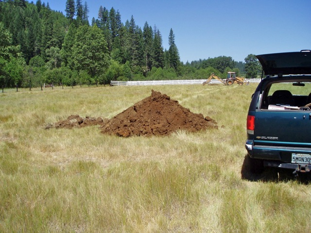
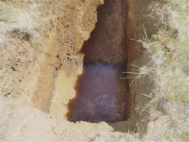
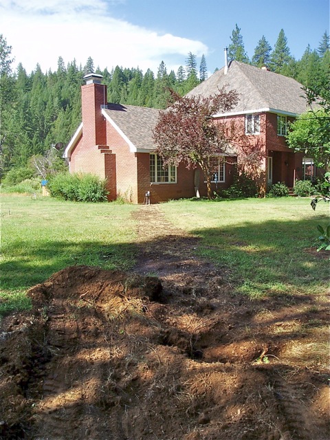
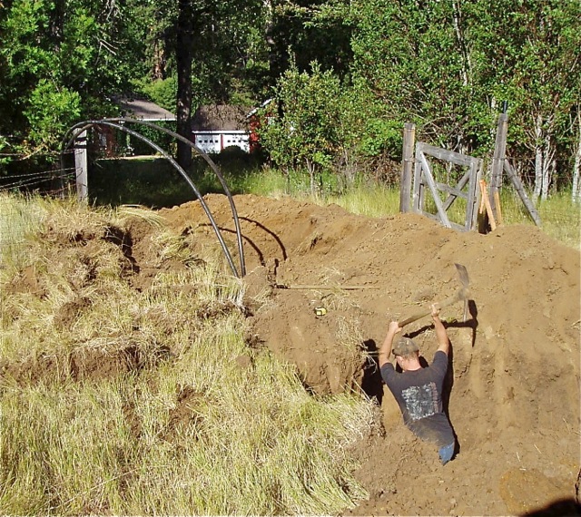
The ground loop was built in an adjacent pasture too wet to support any future building construction. Piezometric monitoring was performed in the winter of '07-'08 which (in a 67% of normal precipitation year) put the saturation level at 40" below the surface on 2/29/08. The pasture's grass is mostly perennial species and remains green through the summer without irrigation; a feature unusual in this Mediterranean climate. Five soil test pits were dug on July 6th. Water was struck at six feet in four of them. Digging of the main loop was postponed until July 23rd, when the trench excavation [six feet wide and six feet deep by 825 feet long] proceeded without moisture from below complicating the pipe loop placement. During this delay, the header trench was dug from the edge of the home to the future header pit at the edge of the pasture.
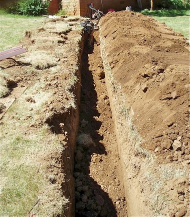
Supply and return headers (1 1/4" diameter HDPE SDR-11) were buried in the header trench, whose total distance of 285 feet to the mechanical room came across 70 feet of crawl space and 215 feet of burial at a four foot depth on its way to the header pit where the main loops were dug in a modified "hair pin" layout. This path was walked several times with a measurement wheel to come up with the desired run length, then both inside and outside trench boundaries were spray painted into the turf for the excavator operator to follow. Across the bottom of the main loop trench's six foot width, seven 3/4" HDPE SDR-11 pipes were spread with roughly equal spacing and no overlap.
Supply and Return Header Trench--
|
Partially filled header trench across lawn reaching toward the house's crawl space. Note the care taken to place turf on left (for replacement) and spoils on the right (on top of plywood sheets to protect adjacent lawn).
|
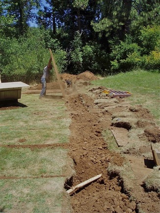
Remainder of spoils now back in trench after having been pushed across protective plywood underlayment. Plywood is now coming up. Trench will be "whacked" with a telescoping compactor and turf will be replaced.
|
Main Horizontal Ground Loop Heat Exchanger--
The header trench was dug by a backhoe with a 24 inch wide bucket, but the greater territory and volume of the main ground exchange loop called for an excavator with a 42 inch wide bucket. Such a machine has more reach, power, and speed for removal, replacement, and compaction of the significant soil volume in this project. A header pit was dug at the common beginning and end point of the seven pipe runs in this loop (about 5,800 feet of 3/4" pipe in all).
The ground loop trench took one day and about two hours the next morning. A crew commenced unrolling the pipe coils immediately, and all were set by early afternoon. Burial began, while pipe fusion at the header pit was completed. Water was used to help with compaction that occurred during two lifts, and the pasture was returned to near normal by the afternoon of the third day. Thus, the loop was secure from the mechanical room out to the loops and back by that time. Photos below:
The ground loop trench took one day and about two hours the next morning. A crew commenced unrolling the pipe coils immediately, and all were set by early afternoon. Burial began, while pipe fusion at the header pit was completed. Water was used to help with compaction that occurred during two lifts, and the pasture was returned to near normal by the afternoon of the third day. Thus, the loop was secure from the mechanical room out to the loops and back by that time. Photos below:
Photo Gallery of ground loop trench excavation and pipe layout.
Click on images below for larger views plus caption. Use right arrow to advance to next image in close-up.
Click on images below for larger views plus caption. Use right arrow to advance to next image in close-up.
Inside the House and Mechanical Area--
With the header set and loop field complete and secured by burial, it was now possible to focus on the inside portions of this retrofit. By their nature retrofits can be far messier than new construction. Duct and pipe pathways are difficult and making alterations from what was there before can be challenging.
In this case, the old underfloor oil-fired furnace and all its ductwork were removed. New ducting was installed and in order to get more air past the 4-ton heat pump's' heat exchanger. To break thermal stratification, an additional air return was incorporated from upstairs to help feed the 4-ton unit serving the main floor. To date, the result pleased the customer.
The completion of this system was by late August and that was early enough for the occupants to enjoy air conditioning for the first time ever in their home. As we moved into the heating season, they have remained happy, now finding comfort in living areas that were previously avoided.
|
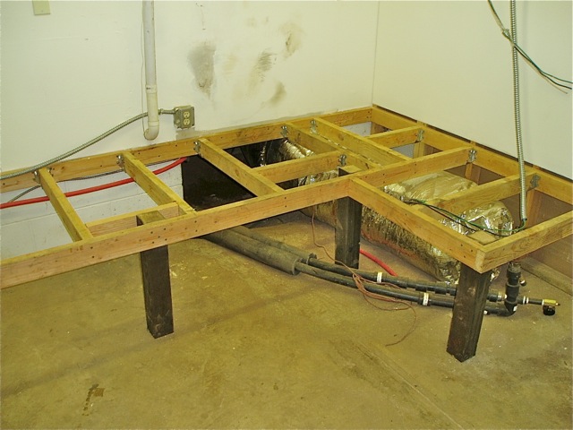
(Above) An above-floor platform was constructed to provide supply and return passages for the 4-ton unit on the main floor, and to carry all equipment.
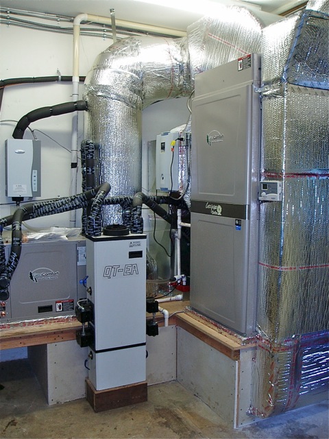
The return air duct is in place. It was joined by a supply duct to its left. The extra return air from the upstairs air handler is in the photo below at the extreme right. (Above and Left-to-Right) Aprilaire Model 800 Humidifier mounted on wall with insulated steam tube entering ducted air stream. On platform, the compressor section of the Geo Comfort 3-ton GST split system unit. QT-EA Flow center with three Grundfos circulating pumps to bring loopfield brine (water plus 15% methanol) to and from both heat pump water-to-refrigerant heat exchangers. Aprilaire Electronic Air Cleaner for the 4-ton unit. White pvc pipes are condensate drains to handle liquid from the air conditioned airstream. The GeoComfort 4-ton GXT packaged heat pump. Humidistat mounted on narrow, vertical duct.
(Above) Connection of de-superheater from heat pumps to the right tank is complete. It pre-heats incoming tap water and sends the product to the left tank for finishing up to desired use temperature. |
(Above) The compressor section of the 3-ton "split system" heat pump. The air handler is in the attic where it serves the upstairs living spaces.
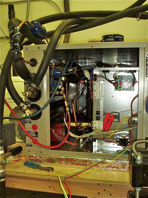
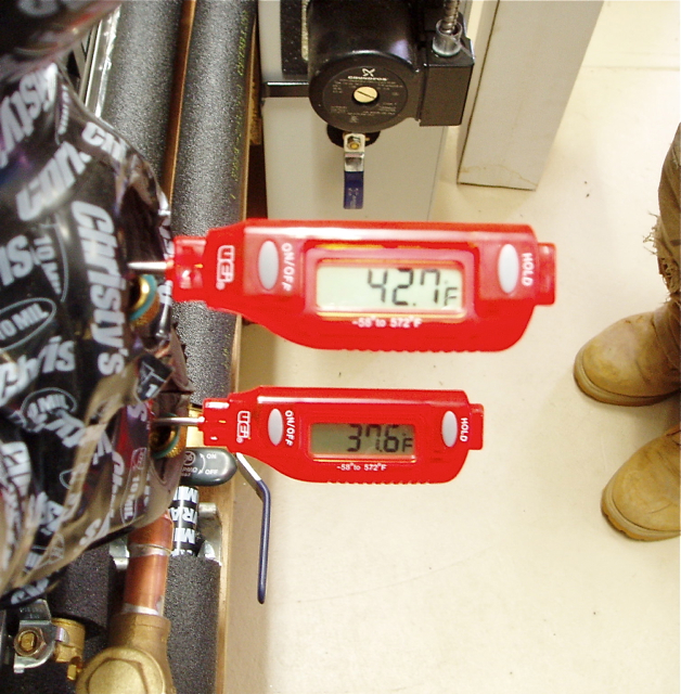
The compressor section uses pumped loop field brine entering and leaving via the two rubber hoses with brass elbows. It passes through the heat exchanger where refrigerant is either evaporated (winter heating) or condensed (summer cooling). The insulated and bare copper line (above the brass fittings) are suction and refrigerant line, respectively. In winter, the insulated line carries hot, compressed refrigerant on its way to the heat exchanger in the attic air handler. Cool household air removes the heat, condensing the refrigerant to a liquid and returning it to the ground loop heat exchanger for re-evaporation to a gas before entering the compressor to become super-heated. In summer, the suction line carries cold, liquid refrigerant that the air handler's heat exchanger evaporates, taking heat from the ducted air stream to do this. A packaged heat pump system has the refrigerant loop pressurized and sealed at the factory; it's all internal to the air handler box. But the split system has two lines which must be uncoiled and connected between the air handler and the compressor section. In the photo above, that connection has been made but the line is being evacuated of its air so that freon vapor refrigerant can be added to this loop without moisture. The red line above is evacuating the refrigerant loop in this system. It's the reversing valve in the compressor section of heat pumps that make the conversion between heating and cooling with one system possible. (Above, 12/28/12) In a hard test run at Stage 2's full compressor capacity, digital probe thermometers reveal the EWT and LWT (Entering and leaving brine temperatures) from and back to the ground loop that was shown in a photo gallery above. The compressor section of this 3-ton unit is taking 5.1° out of the brine to evaporate liquid refrigerant that's on its way to the compressor, where it can be superheated by approximately 100°. Following that, the hottest gas will enter a de-superheater to dump around 4,500 Btu/hr into the larger "pre-heat" hot water tank (left) while the rest of the gas heads for the main condenser to dump its remaining Btus in this pass into the ducted airstream. A 5.1° brine temperature drop here is right on target.
|
