How a Ground Source Heat Pump Works--
The graphics and descriptions below give you a clear view and explanation of what goes on with a GSHP in the heating mode. Additional links to videos can also be seen through the heat pump sub-menu inside the Helpful Links page.
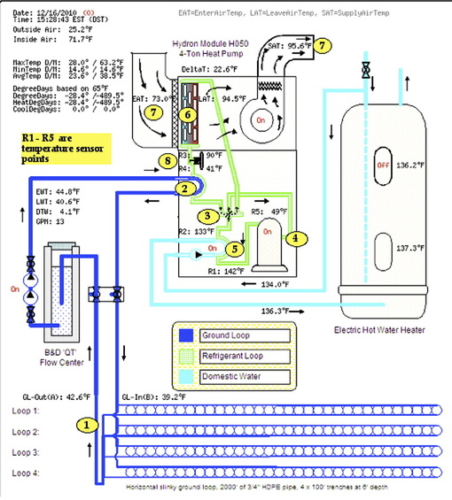 |
This GSHP operates in Madison, VA and the snapshot at left shows the unit in a heating cycle on 12-16-10 at 3:28 pm with an outdoor temperature of 25.2°F. All data is continuously uploaded to the Web and is available for review of real-time operation at the following link: Web Energy Logger #0058 
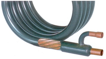
(Above) A longitudinal section of 3/4" HDPE pipe inserted and fused into a 90° elbow. It's a permanent (leakproof) joint.
|
In the graphic "snapshot" of real-time operation (above) we should look at the differences in heat content and fluids in this system. For example, 13 gallons per minute of ground loop fluid is approaching #2. It leaves the EVAPORATOR 4.1 degrees cooler than it entered and heads back underground for another transit through slinky loops.
The ducted airstream #7 represents as much as 1,600 cubic feet per minute passing the CONDENSER at #6. It leaves nearly 23 degrees warmer than it approached. Thus, because of the refrigeration cycle and some electricity, thousands of BTUs per hour come out of the ground and into the home. The reversing valve permits this heat flow to change directions for summer cooling.
The light blue loop circulating from the DE-SUPERHEATER (#5) to the domestic hot water tank can produce 2,000-5,000 BTUs of heat per hour (depending upon the tonnage of the unit). Heating much of your hot water at heat pump efficiency takes a large bite out of the fuel you'll use to finish the process of water heating. Under heavy heating or cooling run-times, this unit may perform the entire job of water heating by itself.
An explanation of the numbered locations above in the GSHP's refrigeration cycle for HEATING
1- Ground loop fluid leaves slinky coils toward the EVAPORATOR at
2; The evaporator gasifies atomized liquid refrigerant on the way to
3; Passing through the REVERSING VALVE on the way to
4; The COMPRESSOR which superheats the gas on the way to
5; The hot water heat exchanger (DE-SUPERHEATER) which takes some heat away, then to
6; The CONDENSER where the gas gives up most of its heat content, becoming a liquid because of
7; The cooler air stream from ductwork which takes heat away from the refrigerant.
8- Liquid refrigerant under pressure backs up at the EXPANSION VALVE and when leaving it as an atomized mist,
cools dramatically before heading to (2) the EVAPORATOR for another cycle.
 |
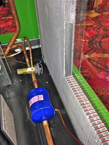
(Left) This is the item that makes it all possible. This is the ground loop heat exchanger (represented as #2 in the above diagram). This device puts warmer fluid pumped from the ground in close proximity to a colder refrigerant mist in these coils. The result is completely gasified refrigerant that can be compressed and super-heated in the compressor. |
|
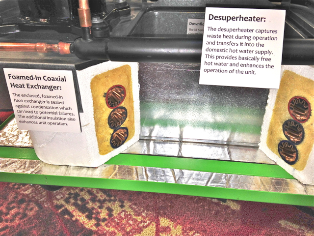
(Right) A cut-away, exhibition model of an Enertech single package heat pump unit showing the main ground loop heat exchanger sandwiched in polyurethane (yellow) foam and surrounded by (white) styrofoam, AND the de-superheater tube-in-shell heat exchanger (black) just above. The sawed-through three coil loop (in heating) vaporizes refrigerant liquid just prior to it entering the compressor. The de-superheater (post-compressor) dumps part of its heat into a water pre-heat loop connected to/from the water heater. |
|
|
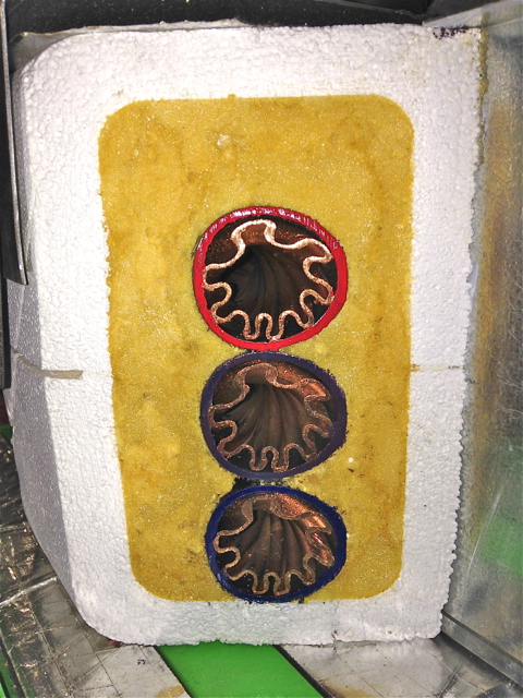
(Left) Ground loop brine on the inside and refrigerant in the small passages on the outside of the double-walled ground loop heat exchanger coil. Three times around and you're good to go! Phase changes (liquid to vapor or vapor to liquid) are where the greatest concentrations of energy are found in nature. Here, the beginning path of water hits coldest (blue level) refrigerant and by the top (red level) the previous atomized, cold, liquid mist is now fully evaporated, ready to head for the compressor. This is where the miracle of phase change takes place. Free "heat" from the ground (at a temperature WE wouldn't think would do us any good, 32-55°F) is plenty warm enough to cause R-410a refrigerant to make the jump to vapor. Post-compressor, this vapor may be close to 145°F, when it can do some real heating work for us. We dump the heat in the ducted air stream (with this model) and "condense" the refrigerant back to a liquid at the fan coil, ready to take up the ground loop's warmth in its next pass. Typically, the ground loop brine goes back underground 5-8 degrees cooler than it entered. |
|
(Right) The vertical, silver fan coil is shown with small refrigerant passages in this cut-away model view. If this looks like an automobile radiator, you're right. We are passing returning ducted air from right to left, through this device. In heating, those small (red painted) passages in the cross section are carrying hot gas, soon to be "condensed" into liquid on the way to the TXV (Thermal Expansion Valve), shown here as a brass fixture with a gray top. Again, in heating, liquid refrigerant under great pressure passing through that gray top will atomize like a Windex spray bottle into small droplets, and chill by as much as 50° on the way to the ground loop exchanger where those micro-droplets will be fully vaporized by the "evaporator." So, in heating, this fan coil is a CONDENSOR of hot gas and the ground loop exchanger is an EVAPORATOR of liquid mist. When cooling in summer, thanks to a reversing valve (not shown here), these two stationary items change functions. Heat from your ducted air (passing through the fan coil on the right) is the power that "evaporates" refrigerant. That gas goes to the compressor, then it dumps loads of heat at the ground loop exchanger, before arriving back here as very cold atomized mist. Walk the numbered circuit above to review the heating cycle. |
|
System Operation Notes
STAGES OF CAPACITY, 1, 2, or 3--
Older heat pump units have a single compressor output level of 100%. Newer "scroll type" compressor units have two levels of output; 67% of full capacity and 100%. The thermostats for the older units would need the ability to control two stages of heating and one of cooling. The thermostats serving the newest compressors would need the ability to control three stages of heating and two of cooling. In both the old and new situations, the top potential stage for heating is one where electrical resistance is added to the plenum's outbound ducted air to "boost" the delivery temperature.
|
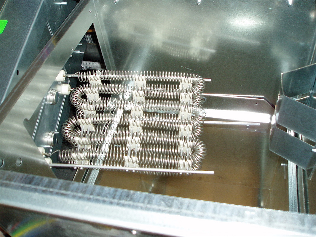
(Right) A 10KW module of electric resistance strips being placed in the outbound plenum of a 3-ton heat pump. Based on need as sensed by the thermostat, half of this 10KW or all of it will be generated (17,000 or 34,000 Btus). It's just a very large, two-speed toaster. |
|
For heating use, a heat pump with a single stage compressor has a 100% of heat capacity as Stage 1 and the addition of some or all of the resistance boost heat as Stage 2. A heat pump with a two-stage compressor has 67% of capacity as Stage 1, 100% of capacity as Stage 2, and the addition of some or all of the resistance boost heat as Stage 3. Resistance heating has no place in the cooling cycle of either type of unit.
A later section of this page (below) will cover the importance of longer run times. For now, we'll emphasize how important it is to NOT set back the thermostat on a heat pump with the intention to return it to regular setting tomorrow morning. When any heat pump is engineered to provide a long run time we know it doesn't satisfy its thermostat quickly (by design). And if we push it upward more than a degree or two, we'll zoom past Stage 1 operation, into Stage 2, and finally into Stage 3 containing electrical resistance. This is an uneconomical practice as resistance heat provides only 25-33% of the Btus per kilowatt hour that the heat pump alone can give us.
A later section of this page (below) will cover the importance of longer run times. For now, we'll emphasize how important it is to NOT set back the thermostat on a heat pump with the intention to return it to regular setting tomorrow morning. When any heat pump is engineered to provide a long run time we know it doesn't satisfy its thermostat quickly (by design). And if we push it upward more than a degree or two, we'll zoom past Stage 1 operation, into Stage 2, and finally into Stage 3 containing electrical resistance. This is an uneconomical practice as resistance heat provides only 25-33% of the Btus per kilowatt hour that the heat pump alone can give us.
Possible Mind-Bender?
Still have trouble wrapping your head around how heat can be transferred like this? You already have experience with the refrigeration cycle with your home refrigerator-freezer. If standing in your kitchen, notice that while operating, your refrigerator dumps up to 1,500 BTU/hr toward you. It got that heat from inside the insulated box you store food in. And because of the refrigeration cycle, that fridge was able to concentrate cold temperatures into the box far colder than the surrounding ambient air temperature of your kitchen. That fridge just mimicked the operation of a heat pump or a standard HVAC unit in the air conditioning mode, except that the insulated box in such a case would now be referred to as your house or building. Here's another explanation by the U.S. Department of Energy that explains how you can get your home's heat from 50° dirt.
The ground heat drives the phase change (evaporation) of the liquid refrigerant, and your cool room air drives the opposite phase change of (condensing) the hot refrigerant gas to a liquid.
A Ground Source Heat Pump moves and concentrates heat this same way in the heating cycle. It takes heat from the ground at a temperature far lower than desired for your inside space—but transfers and concentrates that heat for delivery at 90-100°F through your ductwork. And stated another way, your GSHP (in winter heating mode) is working to chill the ground in the location of your loop pipe, while rejecting that heat to the inside of your home.
Examples of Ground Loop Temperature Dynamics--
Below can be found two data graphs illustrating temperatures present during the operation of a residential ground source heat pump installation in the community of Almont, Michigan (about 50 miles north of Detroit). This residence has a 4-ton heat pump supplied with a ground loop of 3/4" HDPE (high density polyethylene) pipe at a length of 3,200 feet.
The first graph shows operations for the past week, ending January 27, 2012 at 3pm, local time. Ductwork supply air [red] is running in the mid-nineties, and the return air [magenta] is around 70°. When a temperature sample is taken and logged for posting, it is at its peak if the unit is running. Otherwise the reading is posted at the bottom of its "valley" when the duct air temperature has degraded to the ambient level at that location. This posting phenomenon is reversed for the ground loop's brine temperatures. The circulating fluids are far denser than air and hold their temperature longer. The spiked appearance of the bright green peaks are far shorter than the reds (above). The differences in temperature between the incoming brine and its pipes' surroundings are closer because this equipment is usually found in a cold garage or basement (and sometimes a crawl space or an attic). Incoming brine at 38°F is close to a likely garage temperature in the mid-40's that shows up when a timed interval temperature measurement is made when the heat pump is not running.
The first graph shows operations for the past week, ending January 27, 2012 at 3pm, local time. Ductwork supply air [red] is running in the mid-nineties, and the return air [magenta] is around 70°. When a temperature sample is taken and logged for posting, it is at its peak if the unit is running. Otherwise the reading is posted at the bottom of its "valley" when the duct air temperature has degraded to the ambient level at that location. This posting phenomenon is reversed for the ground loop's brine temperatures. The circulating fluids are far denser than air and hold their temperature longer. The spiked appearance of the bright green peaks are far shorter than the reds (above). The differences in temperature between the incoming brine and its pipes' surroundings are closer because this equipment is usually found in a cold garage or basement (and sometimes a crawl space or an attic). Incoming brine at 38°F is close to a likely garage temperature in the mid-40's that shows up when a timed interval temperature measurement is made when the heat pump is not running.
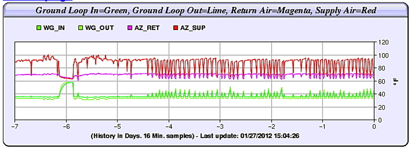
The entering brine temperature (EWT) is the [bright green] and the leaving brine temperature (LWT) is the [dull green] below it. Over a seven day period, these temperatures look to be perfectly steady. But when we step back to an entire year, a clearer picture of ground temperature behavior appears (just below).
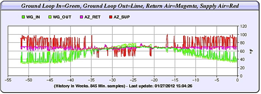
With a yearly perspective, the rolling crest and depression of ground temperature is reflected in the EWT and LWT plots in two green colors. The ground loop brine reached its highest temperature about 25 weeks before this graph was posted, referenced by the zero time point at the far right. At posting time, the EWTs had not quite reached their low point compared to last year at this time (52 weeks ago). Notice also that the [red] supply air "spikes" are turned upward during the heating season and downward during the cooling season. This upward or downward red spike actually represents ground source heat EXTRACTED FROM the ground (upward for heating) and REJECTED TO the ground (downward for cooling).
The highest summer EWT is under 80° and the lowest winter EWT is close to 30°. This illustrates that the ground loop is adequate for this heat pump, in this home, in this yearly climate. Would the heat pump be more efficient if it had a narrower range of EWTs? Yes. But that would mean more ground loop, and this might be a poor investment (as long as the number of hours per year in Stage 3, electrical resistance "boost" was not excessive).
The highest summer EWT is under 80° and the lowest winter EWT is close to 30°. This illustrates that the ground loop is adequate for this heat pump, in this home, in this yearly climate. Would the heat pump be more efficient if it had a narrower range of EWTs? Yes. But that would mean more ground loop, and this might be a poor investment (as long as the number of hours per year in Stage 3, electrical resistance "boost" was not excessive).
Compressors, the heart of the heat pump refrigerant cycle--
The role of a heat pump compressor is always the same; to take R-410A refrigerant gas and super heat it by compression. This function never changes in heat pump operation, summer or winter, but the direction of gas flow does change for cooling instead of heating (or vice versa) by activation of a reversing valve. It is the pressurization of that same gas that circulates the flow in the refrigerant loop.
Shown lower down on the main Heat Pump Page are some schematics and video clips of a 2-speed, scroll compressor by Copeland. Instead of pistons or other mechanisms for compressing gas, a scroll works by a modified spinning motion called orbital rotation. Gas enters a two-walled spiral maze that chokes down its space until entering gas becomes highly compressed—and much, much hotter. After gas pressure climbs to a pre-set level, it is released out the top of the compressor to drive the refrigerant cycle. Those still images and video links of compressor mechanics will make this more apparent. Also present on that page is a discussion of thermostat controls and calls.
Shown lower down on the main Heat Pump Page are some schematics and video clips of a 2-speed, scroll compressor by Copeland. Instead of pistons or other mechanisms for compressing gas, a scroll works by a modified spinning motion called orbital rotation. Gas enters a two-walled spiral maze that chokes down its space until entering gas becomes highly compressed—and much, much hotter. After gas pressure climbs to a pre-set level, it is released out the top of the compressor to drive the refrigerant cycle. Those still images and video links of compressor mechanics will make this more apparent. Also present on that page is a discussion of thermostat controls and calls.
Run Time, the key to lowest overall costs--
Heat Pump Run Time
A GSHP will operate consistently at varied OATs (outdoor air temperatures) because its heat source is the more stable temperature environment of dirt, four-to-six feet under, or in a deep borehole. Based on the heat pump's operational data and varied incoming brine temperatures, the running time at either Stage 1 or Stage 2 operation is the most cost-effective way to satisfy the thermostat. Stage 3 for GSHPs is simply the activation of electric resistance coils in the duct plenum that boosts the leaving air temperature from the heat pump.
A GSHP will operate consistently at varied OATs (outdoor air temperatures) because its heat source is the more stable temperature environment of dirt, four-to-six feet under, or in a deep borehole. Based on the heat pump's operational data and varied incoming brine temperatures, the running time at either Stage 1 or Stage 2 operation is the most cost-effective way to satisfy the thermostat. Stage 3 for GSHPs is simply the activation of electric resistance coils in the duct plenum that boosts the leaving air temperature from the heat pump.
Of course, the basic design attempt is to produce run times for as long as possible in Stage 1, therefore providing an opportunity to gain a larger pre-heated hot water contribution. The run time difference between Stages 1, 2, (and even Stage 3) will be influenced by how the thermostat sets its calls, and how quickly the outdoor temperature drop affects inside temperatures.
Ground source heat pumps can be equipped with a de-superheater to pre-heat DHW (domestic hot water). The process of compressing refrigerant gas is referred to as "super-heating" it. Compression of any vapor always behaves in this way. At the outflow of the compressor, this vapor might be close to 150°F. This is more than hot enough to send to the condenser to be "cooled" by the ducted air of one's home to provide heating. So, some of the super heat is taken away (first) by a small gas-to-liquid heat exchanger to pre-heat hot water.
The de-superheat exchanger allows hot gas to pass in close proximity to a pumped loop from the domestic hot water tank. In each pass, the incoming water might be heated by 3-4°F. The exiting "less hot" gas would head for the condenser at perhaps 130°F, still hot enough for our purposes. Some ground source heat pumps are also built to provide nothing but hot water (usually to heat a home through floor radiant coils). And other GSHPs can actually do BOTH, (ducted air and radiant hot water) and they are called "combination units." This capability is all about the design of the heat exchangers used against the superheated compressor gas.
The financial truth is that if your DHW heating fuel was electrical resistance, then, any of the BTUs you gain through the de-superheater were gained at the same COP of the heat pump. Therefore, we can pre-heat hot water with the de-superheater at 1/4 (or less) than the cost of straight electrical resistance.
